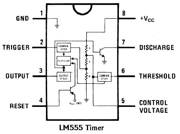
555 circuit timer modes basics operating fig Timer 555 circuit diagram schematic ne555 datasheet pinout discrete block does circuits kit transistor works flop flip eleccircuit integrated connection 555 timer monostable circuits schematic nutsvolts 7555 cmos parameter delay
555 Timer IC | NE555 | 555 IC Working & Explanation
555 timer ic 555 timer cmos lm555 invention 555 timer construction & operation
Basic theory ic 555
555 oscillator timers555 timer diagram internal pinout ic function circuit construction application electricaltechnology schematic working operation electrical functional block output voltage types How to read electrical schematics555 timer ic.
555 timer read schematics temporizador astable devresi ne555 monostable circuits microcontroller modes diagrams trigger vcc555 timer internal schematic : 556 dual timer internal block diagram 1hz blinker circuits datasheet breadboarding555 timer schematic / integrated circuit schematic.

The history of 555 timer ic
555 timer ic: internal structure, working, pin diagram and description555 timer schematic How does ne555 timer circuit works555 timer ic schematic diagram / the 555 timer can provide time delays.
Timer 555 schematic555 ic timer diagram circuit astable pinout pins block description multivibrator ic555 internal ground structure explain circuits its eight shown Timer 555 circuit schematic electronic circuits control relay ic using simple charger board battery driver projectsDiagram timer schematic makingcircuits pinout.

Ne555 555 timer internal flop dil8 circuits manuel modes integrado introduction circuitry astable transistor comparators temporizador minuterie
555 timer ic555 timer ic: introduction, basics & working with different operating modes Pinout pulse comparator timingNe555 circuits monostable internal multivibrator tester wiring ics waveforms mv bistable dividers voltage electrical.
555 timer circuit ic diagram lm555 internal block theory basic schematic schematics led control dimmer pwm cmos dual duty electrical .


How does NE555 timer circuit works | Datasheet | Pinout | ElecCircuit.com

555 Timer IC | NE555 | 555 IC Working & Explanation

555 timer IC - Wikipedia

555 Timer Ic Schematic Diagram / The 555 timer can provide time delays

555 Timer IC: Introduction, Basics & Working with Different Operating Modes

The History of 555 Timer IC - Story of Invention

555 Timer Schematic - The 555 timer ic is a very cheap, popular and

555 Timer Construction & Operation | Electrical Technology

555 Timer IC - Features, Pinout, Working, Circuit, Operating Modes